Your Showmaster Video Colorizer May Not Be Dead
Showtime Video Ventures: A Preamble
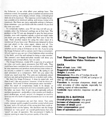
I’ll preface this slight how-to blog by unashamedly stating I’ve been a fan of the gear that Showtime Video Ventures produced and released ever since I picked up my first ‘black box’, an Image Enhancer which can sharpen or smoothen video .
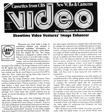
From what’s available online – and it isn’t much – the company was presumably founded in the late 1970s. There’s a listing for 2 trademarked names – a Syncalyzer which stabilized rental tapes when viewed on a TV set, and a Vidiot, of which there’s no other info – but in a Sept. 1980 issue of Video Magazine, their Enhancer is given an overall positive review. That product originally listed for $299 SRP, so it’s fair to bet SVV’s products were aimed at the then-seminal prosumer market – early adopters of recording and playback gear searching for feasible methods of improving image, and to some extent, sound.
There used to be a great site that listed *all* of SVV’s products – catalogue numbers and rough description – but as often happens with sites, it’s gone, taking with it a valuable resource of information that outlined the company’s extensive product line which gained notoriety when it launched it’s own gizmo that defeated copyguard.
Issues of Video magazine and Video Review magazine had classified ads in the back for video enhancers, correctors, and whatever nomenclature alerted video fans that the gizmos could get rid of tearing at the upper image when playing back rental tapes, and yes, subvert copyguard.
When SVV folded isn’t clear – it seems they were doing quite well up to the late 1980s, marketing a broad variety of products designed to enhance, amplify, duplicate, convert, mix, and colorize signals, either in black box form or in rare cases, a gizmo you attached between your camera and VCR. (That gizmo existed as an enhancer and separate color corrector, and I used the latter for a short film, because it was helpful in tweaking and boosting weak color signals from a tube camera.)
Over the years I’ve gathered a substantive amount of the company’s products, plus some manuals and catalogues, and saved images from rare oddities posted for sale at often stupid prices with ridiculous international shipping.
In no way is the following a detailed explainer of how a Showmaster Video Colorizer works. I’d like to reserve that bulk of info for a future video if plans for a proposed Patreon channel come together in the fall, but I did post a series of minute-long videos on Instagram, briskly spotlighting the Colorizer’s core features .
The following info may help those who gambled on a Colorizer and found it either twitchy, non-functional, or became such over time.
Perhaps the Colorizer’s closest contemporary parallel might be some of LZX’s products; SVV’s gizmo tints a video input and allow the largely primary colors to pulse according to audio inputs.
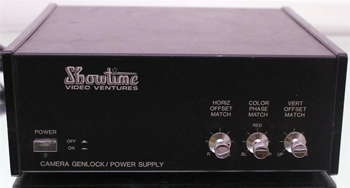
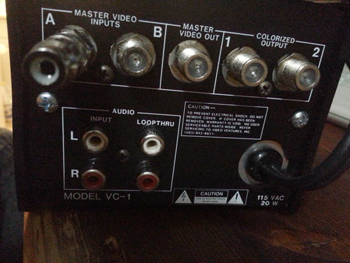
SVV’s gizmo follows the company’s physical design of using custom components – you’ll notice the knobs and switches are the same as other black boxes, and their video mixer – as well as their proprietary logic of eschewing RCA composite video inputs for coax connectors identical to the screw-on RF connectors using coax cables. My guess is they felt the fatter copper cable offered better signal, and they also sold their own cables, which mandated the use of coax for video, unless you hopped over to Radio Shack and grabbed some from them (which I frequently did for my own needs during the 1990s).
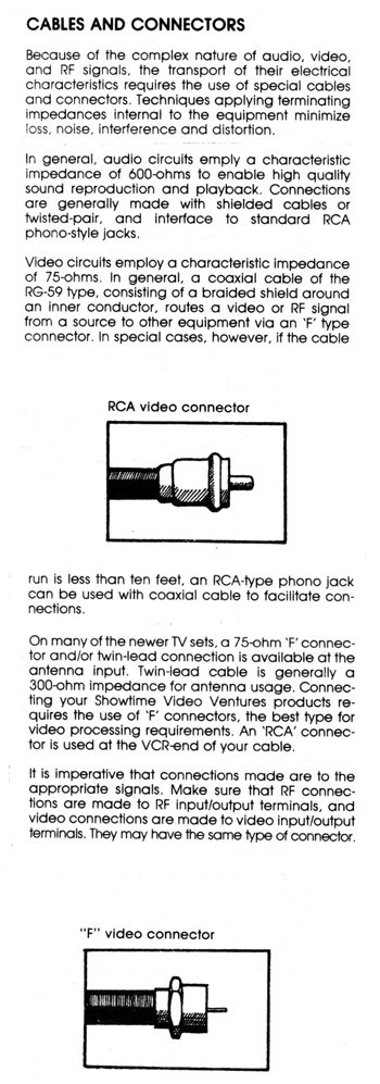
In any even, the Colorizer’s audio inputs are RCA, and the video are coax, and they’re for composite video, not RF, even though some of the black boxes do contain clearly identified RF outputs for TV display.
I first heard about the Colorizer when I stumbled upon Chris King’s Video Circuits page that showed the colorizer, a mixer, and a genlock box that came up for sale. Here’s the first threesome image:
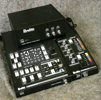
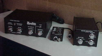
And here’s another threesome that I actually bought from this vendor, which contains a switcher box (not useful for my needs), that image enhancer, and that color processor which you fitted between the video camera and VCR:
From my initial research, the Colorizer sold around 2007-2008 on Ebay, and then nothing appeared for more than half a decade until a new old stock (NOS) unit showed up, which I grabbed ASAP. That one functioned perfectly, and came with a manual that’s as eccentric as their manual for their other products. My second Colorizer showed up maybe a half year later, and it too worked… but then started to get funny, losing sync from the video input, and then becoming unusable.
Soon the NOS unit started to have issues – the colors were off, and there was a persistent vertical offset that appeared regardless of whether you turned the unit on / off, ran through various switches, or yanked out the video inputs for a moment.
The Showmaster Video Colorizer: How the Gizmo Works & the Not Really Big Fix
The following section identifies the innards of the unit and those potentiometers I was able to identify, but I make no warranty as to whether it’ll work or cause damage. Proceed at your own risk; what follows is exclusively what worked for me.
First, a basic primer on how the unit works:
It accepts up to 2 switchable video inputs and one stereo audio input, and will loop out the original ‘clean’ video, and has 2 outputs of the colorized signal. As per the manual, these outputs were designed for use with their mixer, the Showmaster VSEC-1, which is loosely advertised has having a synchronizer *but does not*.
That model deserves and will get its own video, but be forewarned: you can dissolve and wipe between the colorized and clean signals from this unit, but forget about connecting 2 consumer VCRs for mixing – they need to be genlocked, and that’s another video subject, given their separate genlock / camera power supply box is very, very weird.
Here’s a rough scan of the schematics of gear ‘recommended’ by SVV to maximize your video needs:
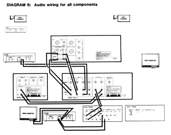
That’s 2 VCRs and / or cameras + genlock + colorizer + mixer + color processor + audio / visual processor + monitor(s). Diagram 6 ‘suggests’ the addition of a Systems Switcher.
Overkill, right?
First point: while you don’t need audio to make the image pulse, you absolutely need a stable video input, or you get gibberish. The unit will not output even its own color bars preset unless you’re sending it clean video, either from a camera or VCR.
Second point: although you don’t need to input audio, the unit’s own pulsing oscillator offers a stable pulse which you can slow down and speed up, and adjust its volume. I’d use it more for testing the machine’s colorizing feature than anything else, or perhaps when using the unit for some background plates that can randomly pulse.
Third point: whatever setting you found that yields pulsing colours will *not* be saved after the unit is turned off. Yes, you may have left the 3 lower knobs alone, but you have to restart by letting the unit ‘see’ the audio and then make slow adjustments to the video and audio until an image starts to appear and pulse. (See the Instagram videos demonstrating camera-fed footage and the abstract pattern the unit generates, Part 1 and Part 2.)
It’s an odd process, because you have to wait for the unit to sense the audio, which can be hastened if you crank up bass; bear in mind that you still have to find a sweet spot between you music source’s volume and the Colorizer’s volume setting to get things pulsing.
Fourth point: the unit is really sensitive to what doesn’t seem like broad turns of the knob; in other words, it’s easy to lose or smother a color-pulsing image, and takes a moment to get it back because it has to ‘re-sense’ the inputs.
The prosumer aspect of SVV’s designs and target buyers mandated the addition of extra features, so the order of display choices the Colorizer offers are:
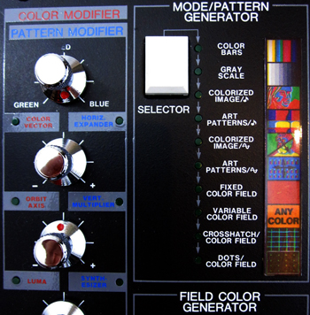
Color Bars
B&W Bars
Colorized Image (Video Input A or B that pulse to the inputted audio)
Art Patterns (abstract graphic patterns that also pulse to the inputted audio)
Colorized Image (which pulses according to the internal oscillator)
Art Pattern (which pulses to the internal oscillator)
Fixed Color Field (selectable color backgrounds)
Variable Color Field (which you create by alternating 3 upper knobs)
Crosshatch Pattern / Color Field (to check tube / monitor and the unit’s alignment)
Dots / Color Field (to check tube / monitor and the unit’s alignment)
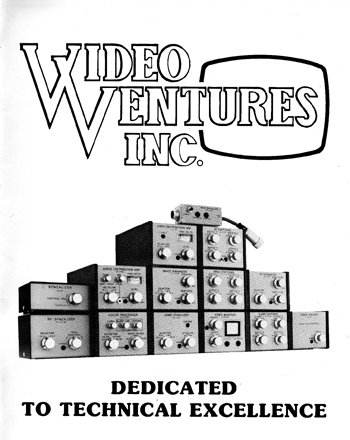
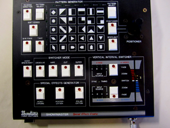
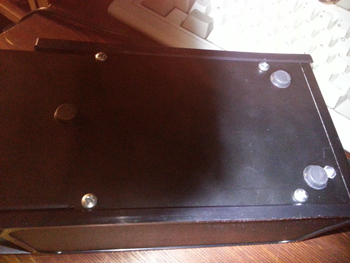
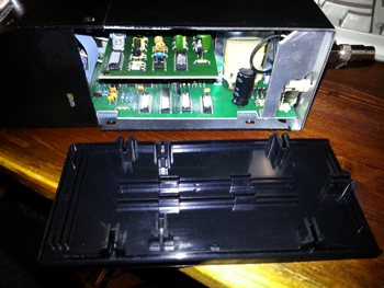
If you look at the pictures of gear way up top, you’ll see the black box design includes similar plastic side panels, top sliding panel, and front knobs / potentiometers that require the use of a small screwdriver to tighten if they get loose and are misaligned.
The Colorizer features a similar design where assorted screws will loosen panels, and it’ll allow you to ultimately peel out the small circuit board in the upper rear which houses three important potentiometers, made by Piher Spain.
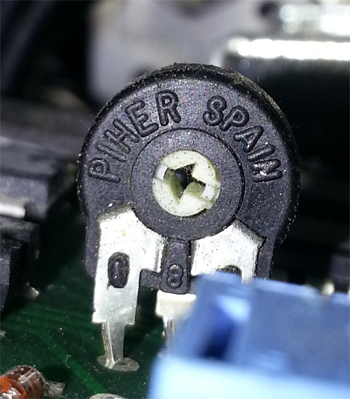
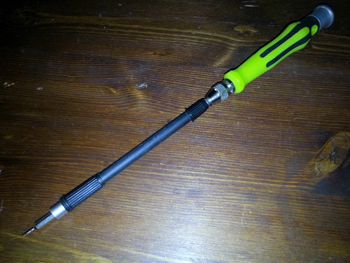
I used a small Phillips tip attached to a flexible screwdriver attachment to do tweaks, but bear in mind a) these are (obviously) non-hex pots with non-incremental positions; b) some of the pots are located in cramped corners; and c) you tweak at your own risk.

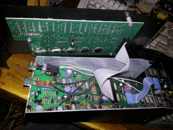
These are the *only* screws you need to remove to gain access to the circuit boards
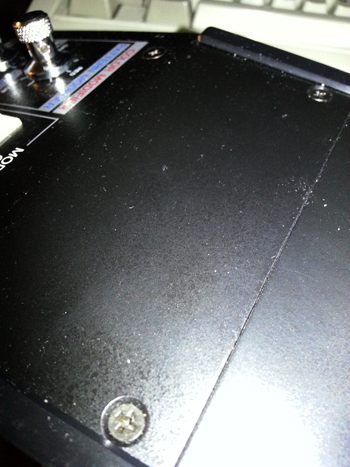
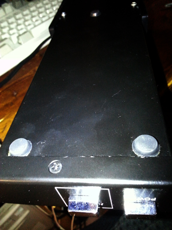
Sections to be removed:
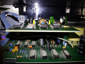
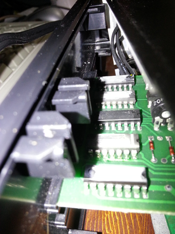
Splayed circuit boards:
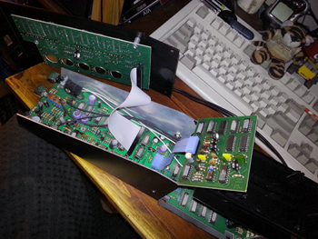
When you peel out the sloped and small circuit boards, make sure you have cardboard or one of the plastic side panels between the exposed boards and the unit’s case – I almost zapped the small circuit board when it briefly touched the upper metal case.
As both images show, the sloped panel with the switches and knobs also comes out, and has 1 pot.
Audio & Video Connections
With everything splayed out, here’s how I did my tweaks while the unit was connected. The main video source was a video camera; audio was from a stereo receiver; one colorized output went to a CRT monitor, and the other into an LCD widescreen monitor (that connection was Colorizer to Toshiba DVD-R recorder, and Toshiba to LCD monitor via HDMI, and the monitor set to 4:3).
As a test, if you disconnect your video input, you’ll see the image turn to gibberish, and when you put it back, the image is stable – a clear example of how much it relies on a stable video signal.
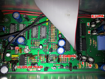
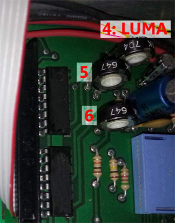
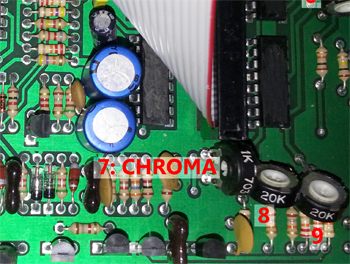
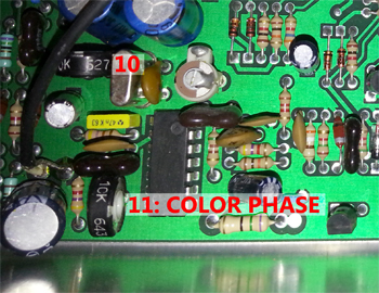
Here’s a series of highlighted stills of the circuit boards and what pots I was able to identify. The unknowns I did tweak, and assume they might be to control the internal oscillator volume, the audio input volume, and maybe signal outputs.
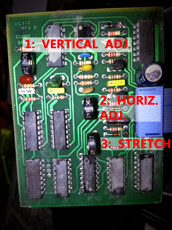
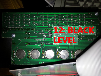
To fix my gibberish unit required going back & forth between the identified pots. I touched the black level (located under the sloped panel) once, but the others I tweaked because the horizontal sync was mush.
The steps that seem to have worked involved displaying the Crosshatch pattern, then adjusting the vertical sync so there’s a stable visual element to enable adjust the horizontal. This edited footage of the main tweaks give an idea of some of the visualclues to observe as you adjust the identified pots:
Vimeo:
YouTube:
One quirk with SVV’s products is the inputted video signal can be faintly seen under a colored image or even colored background, and as with their mixer, the edge of the image being mixed over will appear at the edges in the overscan area that’s wholly visible when you capture video to a hard drive. (Slightly magnifying it to 105% eliminates the overscan.).
Because the horizontal axis on my units was screwy, it puts the image border that has color burst and other info smack in the middle of screen. That actually enables you to see the inputted video at the frame edges, but as excerpted in the above video montages, adjusting the horizontal video pot will center the image.
When you adjust the vertical pot to one side, the frame rolls up, and you can see the clean video input in the blank border that divides the frames upper and lower frame edges.
Additionally, if you adjust the image stretch pot, you can compress or stretch the image within the frame without the stretched image bleeding past the right frame edge, which makes me wonder if you could adjust an anamorphic or modest widescreen image to fill the 4:3 frame like CinemaScope, and after capturing the footage digitally, stretch the 4:3 image back to its original or intended widescreen ration. (This of course would mean cracking open the unit again, unless you hack the pots and put potentiometers on the slanted board, or top panel.)
Back to fixing.
To properly center the image, go to the Crosshatch pattern, and make final adjustments using the horizontal and vertical pots. For vertical, try and get two solid horizontal lines at the frame edges using a monitor that shows overscan, as a misaligned CRT tube will make you choose inaccurate settings.
Then adjust the Crosshatch using the stretch pot so there’s 19 vertical columns; don’t include the vertical columns at the frame edges. I suggest 19 because when you switch to the Dot pattern, there’s 19 vertical columns of dots in the screen centre.(Adjusting the stretch pot doesn’t alter the dot pattern, so I use it as a reference point.)
For the above adjustments, note that the smallest tweak of the pot can make it jump, so it takes a few tries to get the most centered image possible. Also, while this didn’t happen on my LCD monitor, both Crosshatch and dot patterns sometimes twitched or jumped, with slight tearing at the top frame. This may be due to the higher contrast between white grids on black background, and on older CRTs it might both twitch and yield a high pitch squeal from the TV’s oscillator.
Small interjection: prior to centering the image, I also fiddled wit the color burst and luma levels (also in video montage) because it seemed getting the unit to ‘see’ color bars enabled me to fiddle with the horizontal & vertical pots.
The circuit board pots I’ve identified – 1) vertical adj., 2) horizontal adj.; 3) horizontal stretch; 4) luma adj., 7) chroma / color burst level; 11) color phase adj.; 12) black level – are very similar in scope to those on SVV’s black box video processors: they have very wide ranges that drain color or blast it to outrageous levels; the phase adjustments are sensitive; and the luma levels range from blown-out bright to a threadbare signal that has a hint of sync before it’s gone.
The Colorizer’s circuit board pots are very similar, so when adjusting the luma, bear in mind the range goes from bright to dead, but a few beats before dead there’s a weak B&W signal, and a few beats before that you’ll get a kind of messy color layer; make sure you set the luma a little before that so the brightness level is closer to normal.
In none of these alignments did I use a vectorscope because a) I decided to do these tweaks spontaneously; and b) you can eyeball the levels. The reason I’m fine eyeballing levels with Showtime’s products is because I use them to blast or drain luma, phase, color burst, black levels, and whatever’s outside of ‘legal’ levels. I use them to mess up and alter, not accurately align.
So wrapping up the last of the tweaks, I’d adjust the color level using what should be centered color bars, and then adjust the color phase. There’s a *very* thin distance between accurate and off, and when you see a clean red color bar and all colors have max brightness and saturation, *stop* adjusting. That’s as good as it gets when you eyeball.
Lastly, run through the various options on the sloped plate, switch between input 1 and input on 2 regardless of whether there’s a video input, and turn the unit on / off. I suggest this because the color bars are always loaded first when the Colorizer’s turned on, and I found the color level might be what affects the vertical sync. You maybe have to tweak the pot a bit, switching between selections again and going on / off until there’s no offset.
When you turn on the Colorizer, you should get clean stable color bars, and clean displays of the colours and centered dots and crosshatch patterns as you switch through them.
Also check that when the inputted audio makes the colors pulse, it also doesn’t create a vertical or horizontal offset. On my NOS unit, the problem would reappear after a period of use. These final pointers are to make sure you don’t have a recurring offset and must crack open the unit again, because it’s a pain to open up, and a greater pain to reassemble.
Make sure you reassemble the unit with the power out, and the audio & video plugs pulled out.The slope panel is easy to reattach, but the small circuit board conected to the main fixed board by a narrow cable is not, and requires fipping it and lightly pulling back the upper case so it slides in.
You also have to snap the opposing plastic side panel in place, and stick the small circuit board in a groove that’s not close to the rear power supply. It should fit as so, at the end of the thin slot
Snapping the other plastic panel’s tricky, as you can either let the end of the small circuit droop above or below that think groove, or try and nudge it in place before snapping the panel, the upper case,and the sloped segment in place and tightening the screws.
Check for bulging corners, as those plastic panels keep everything tight. Be gentle during reassembly, as a busted groove won’t enable panels to sit firmly, and the screws rest between two plastic clips, not a bolt or socket, so make sure you don’t force them or wear them out, loosening the panel’s grip.
Again, these steps helped my fix my units, but I offer no warrantees, and the risk is yours alone in attempting to fix what is a unique gizmo.
Feel free to post comments here, on the Big Head Amusements Facebook page, or my Instagram page, and / or shoot questions which I’ll try to answer, and as I make better use of these and other SVV products, the material will be fodder for standalone Patreon videos whose purpose is to show how analogue video that shows up on assorted sites works, and how it can be used with digital gear.
And both my Vimeo page and YouTube channel have assorted video tests and oddities for which I used several gear from Showtime Video Ventures.
Finally, this entire blog and the curiosity to address a lingering thorn in a great gizmo came from a query by Austin Settle. Please check out his Instagram stills and sample his fine video art at https://www.austinsettle.net.
Thanks for reading, and Good Luck!
Mark R. Hasan, Editor
Big Head Amusements