Gear Tests: Vintage Systron-Donner Data Pulse Generator, Part 2
In Part 1, I posted a few snapshots of the Systron-Donner Data Pulse Generator, plus how to fit an AC cable into a socket, since most gear todays tend to use the more rectangular 3-prong plug, but let’s get into the first question on your mind: Why get a data pulse generator?
Video artists have a substantive selection of modular audio and video synths available, but being on a budget, dropping heavy cash for a LZX gizmo to create pulsing lines can easily get close to $1000 U.S., and as the Canadian dollar continues to hover around 73 cents US, the days of snapping up gear from south of the border is less frequent, especially when shipping costs from the US to Canada can be more than the other way around.
As I cited in Part 1, early electronic composers found they could create sounds using oscillators – lab test equipment that emitted precise tones – and a data pulse generator’s somewhat similar in being able to output precise signals, although instead of woo-woo sounds, you get static blips that can sound like a tone when the frequency’s cranked up.
A lot of this vintage gear is readily available via Ebay at various costs – mine worked out to about $70 CAD plus shipping from a vendor in Ontario, which is cheaper than a Eurorack modular component – but there are key questions that aren’t easily answered online:
1 — What is it? You can find intriguing gear online, plus a variety of pictures for certain units, but as to what some of these old things do is much harder. If it’s lab gear designed to test circuits in conjunction with oscilloscopes, you’re more than likely to stumble across tech talk that’s far beyond your scope unless you’ve a good understanding of electrical engineering. I don’t, so the search for plain language descriptions of a unit’s purpose and functions are ongoing.
2 — Can it be used to create video art? If the available info is highly technical, you might not find a clear answer. You may find the odd post in a specialized forum, but more often than not, it’s technicians or circuit benders who may create or adapt existing gear for their purposes, and finding a post that even mentions your specific model (or even the manufacturer) is rare.
3 — Whether your intended use is for a combination of audio and video art, not all vintage gear with big knobs are usable. The range of sounds are limited, and to get certain visual patterns you’ll need to chain together a variety of things which modular A/V synths can achieve in smaller design with a greater variety of options with looping cables (hence their higher cost for their sheer versatility and features that more directly fill the needs of artists).
So as to the Why, the answer is part cost (assuming it works / was tested by the vendor), curiosity, and the potential to find options that are unique and perhaps not readily available on contemporary modular units. There’s also the aesthetic value and attraction of a vintage design that differentiates itself from small gear. Some people like cables and knobs, others like everything in desktop unit.
Of course tied to What is it? is a need for a manual, and it’s rare when a unit comes with an original. They can be found online as scanned PDF files or original hardcopies on Ebay, but the language within those manuals may also require an above average grasp of electrical basics, at least with specific nomenclature.
This post covers the first three test videos I created live, just to see what happens when you generate pulses, send them into a waveform monitor, use the monitor’s video out pot to send a video signal to a video mixer, apply vintage digital effects live, and record the whole thing to disc before layering, colorizing, and rendering in Adobe Premiere.
This is very much a work-in-progress, and after every test I have to strike the setup because of space issues, but to record pulsing lines takes some careful thinking to ensure you don’t end up with a mush of bad sync material that’s utterly useless.
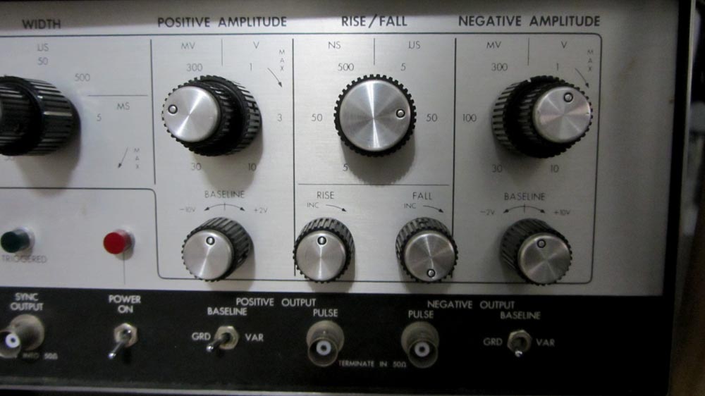
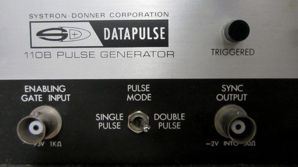
The Systron-Donner 110B is one of many models the company produced that offered test signals, and this particular model offers switchable single and double pulse (beats) mode. Sonically, there’s no overt difference between the two settings; this unit outputs steady pulses, not musical synth beats.
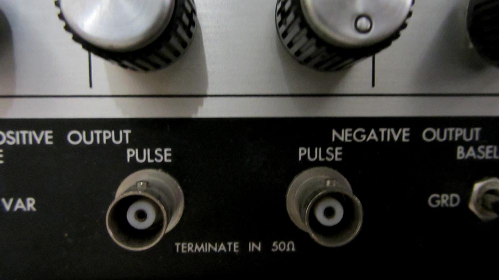
The 110B also outputs whatever you’ve set up as a positive and negative signal, presumably allowing you to send the two simultaneous signals to an o-scope and use them as reference to whatever circuitry you’re testing. Sonically, there’s no difference, but when the signals are displayed on a scope in tandem, you’ve got a pair of visual lines that can add a bit of variety, either stacked on top of each other in the o-scope’s Dual mode, or in Add, which blends both into one pulsing signal.
The unit also has a large fan, dead-centre on the top mesh to keep it cool, so presumably it can run for long stretches. I tend to plan out short tests to figure out the proper routing to get specific visual patterns before setting aside an hour or two at most to do long-form tests; it uses less energy and doesn’t overtax what’s clearly vintage gear that may have been used only occasionally before it was mothballed, sold to a vendor, and bought by you.
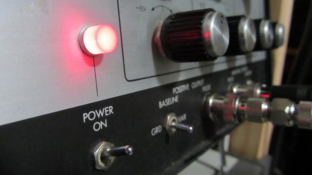
All knobs are on the front panel, as are the BNC connectors to send in a trigger input (something I still have to figure out) and output those positive / negative signals.
As I mentioned, routing a recording is a bit complicated because you’ve two options: film the squiggling waves off a scope’s monitor with a video camera, or use a video output on the rear of some models to record the visual signal.
O-scopes have front inputs for the signals you want to display (A and B), and some models have a Z-input in the rear which also accepts a signal, whose intensity will boost the brightness of the ‘scope’s display.
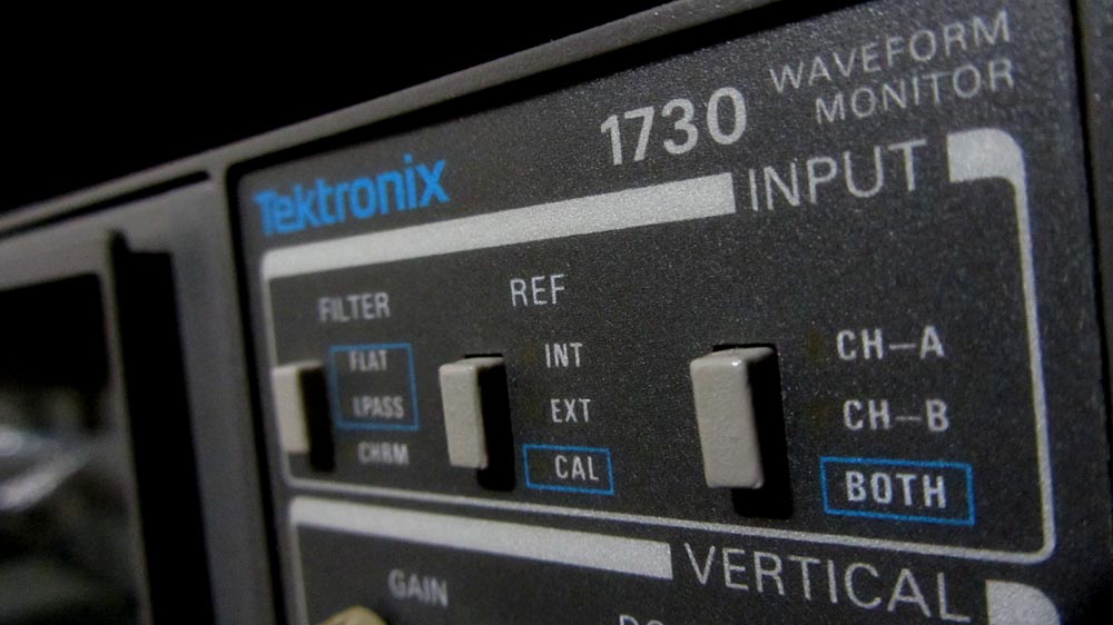
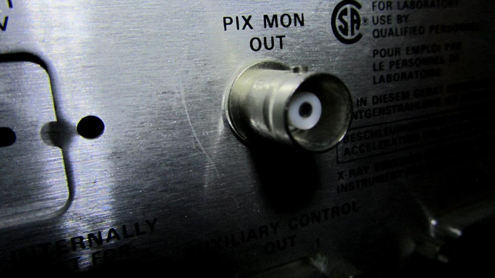
The Tektronix waveform monitor (model 1730) also has A-B inputs, but no Z input. It does come with a Pix Monitor Out BNC socket that’s kind of a Z-input in reverse: it’ll display lines on a CRT monitor according to the signal’s brightness. Ergo, if you send audio into the A or B (or both) channels of a w-scope, the image on a monitor will brighten, especially if you crank up the audio’s volume.
However, this outputted B&W signal lacks any horizontal sync, meaning if you plug the w-scope’s Pix Out into a video mixer, you either get gibberish, an image that scrolls, or an image split in two with the centre median in the image centre.
This signal cannot be recorded into anything usable, so you’ve two choices: record the pulsing B&W lines off a CRT tube with a video camera, or add sync to the unstable signal so the mixer will recognize it.
It’s true vintage mixers like the Panasonic WJ-MX12 have built-in synchronizers, and it can accept some measure of garbage video – it was able to accept video from a Hi8 camera I have that’s riddled with rotten capacitors – but we’re talking no sync from the w-scope, so here’s one method that works, and it involves sending clean blackburst (black video, aka BB) from a generator to the connected gear.
This mimics a broadcast setup in which two cameras are genlocked to each other and a video mixer to ensure clean wipes and mixes. The following steps worked for me, but as a standard caveat, follow these at your own risk:
1 — Output the positive & negative outputs from the 110B to the A & B inputs of a w-scope.
2 — Connect the Pix Mon Out on the w-scope’s rear to Video 2 input on the video mixer. Make sure the input switch is for component video, not S-VHS.
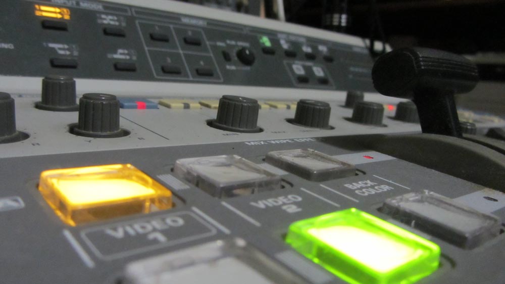
3 — Connect your BB signal from a generator to the mixer’s Video 1 input. (In place of a standalone generator, I use the BB from a Tektronix 1410 generator.)
4 — Connect the video mixer’s Sync Out to the w’scope’s Syn Ref In plug.This genlocks the w’scope to the mixer and enables it to accept a signal with vertical sync that’s recordable.
5 — Then connect the video mixer’s Output 1 to a monitor so you can see what it’s getting, and Output 2 to a DVD or analogue tape recorder that in turn outputs to a standard LCD monitor.
Why not use a firewire converter like a Sony GV-D1000? Because the video levels will be so insane (and possibly have synch issues) that more sensitive gear requiring rock solid video signals will get blocky or blank, making the footage useless. VCRs will stabilize bad video if recorded to tape, and a DVD recorder (like Toshiba’s solid-as-a-tank models) will do the same.
Once you’ve recorded your footage, dump it to the hard drive through a separate firewire connection, or rip the DVD.
Recording the video with audio is a lot trickier, and once again I make no claims this is foolproof. Try this at your own risk.
Many vintage test devices have a variety of unique inputs & outputs, and as neat as some gizmos may seem, I’d argue only a few offer the possibility to create interesting images / sounds. I always check if there’s a video on YouTube in which a technogeek (a professional engineer) explains how a device is used; if there’s a mention of high output that can damage sensitive modern gear, stay away from it.
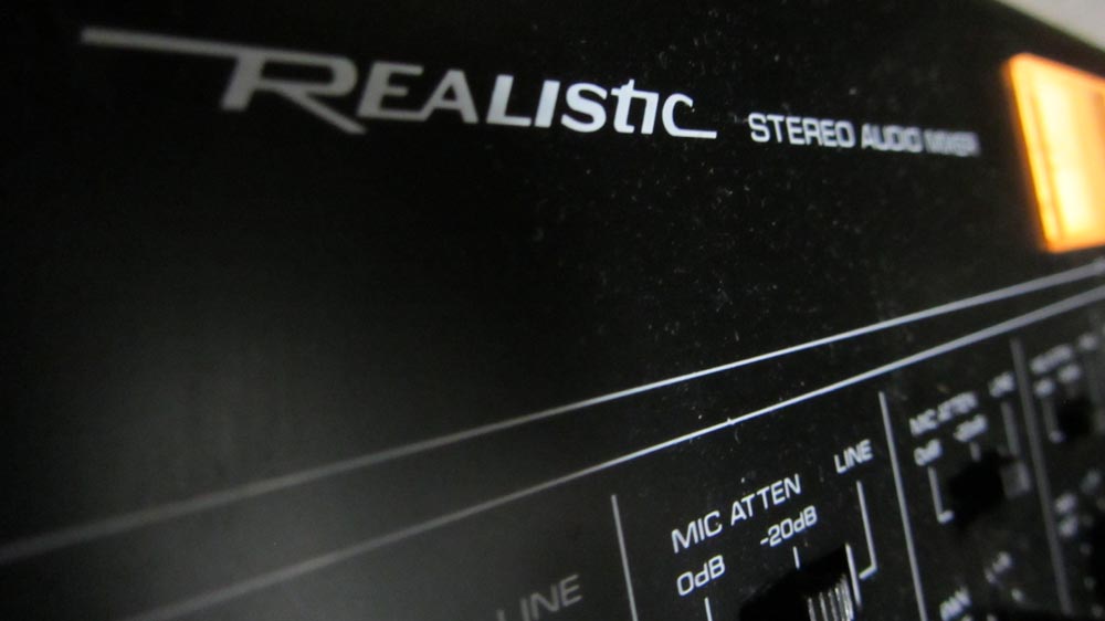
I assume the 110B’s signal should be attenuated for any kind of audio recording, so I used a Y-cable to split the positive output, tipped the end with a phono adapter, and plugged it into an old Realistic stereo mixer I bought back in university for film projects (which still works swell).
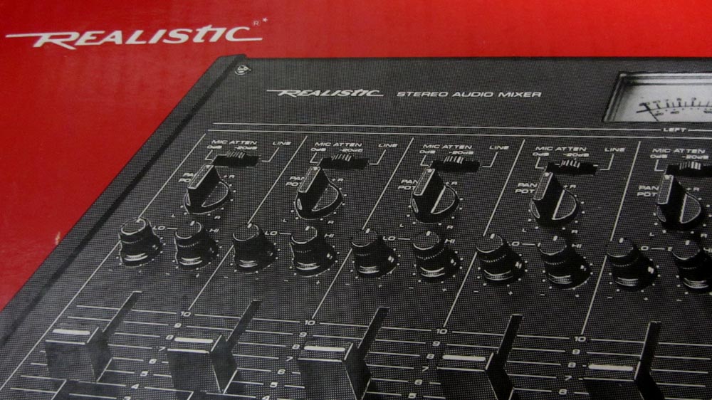
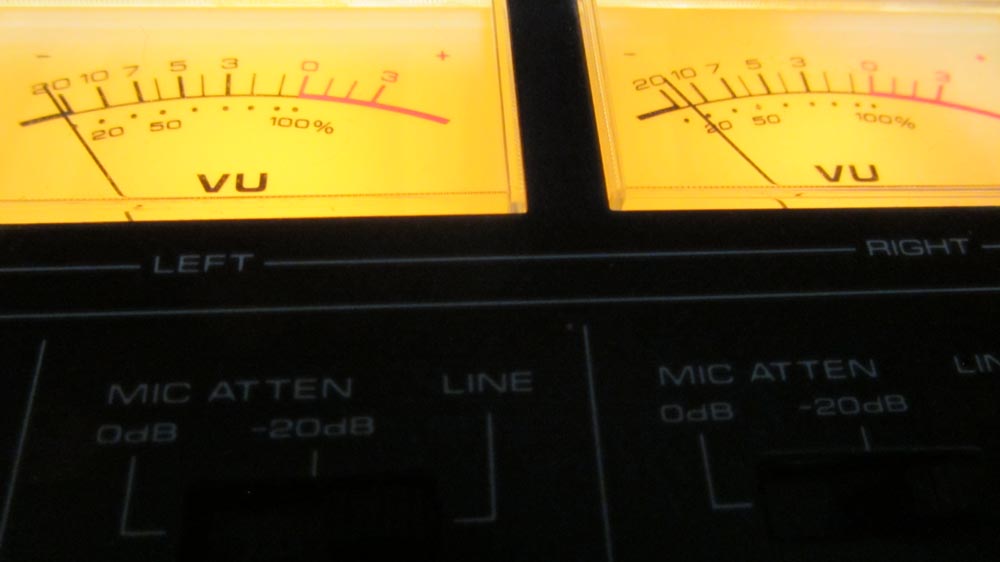
For Line 1, I used the mic attenuate setting (-20 dB), and gently moved the Line 1 and Master out pots up until I could see a steady beat or signal in the VU meters, and kept it close to the red zone’s tip. (Use the w-scope to see a steady signal, and use the audio mixer’s VU to set the levels for audio output.)
I then connected headphones into the audio mixer, and gently turned up the monitor input until I could head the audio. Do not crank up the headphone volume – as you change the 110B’s pulse frequency, the pitch will increase as will the volume.
You want to make sure 1) you don’t blast a shrill noise into your ears, and 2) make sure that as you adjust any settings on the Systron, you can adjust the Input 1 volume to keep the pulse close to the tip of the VU’s red zone.
The Panasonic WJ-MX12 mixer does have audio input / outputs, but 1) on my unit, I can hear the inputs, but it wasn’t outputting any audio, and 2) I’d rather risk damaging an old Radio Shack audio mixer than the Panasonic.
To wrap things up, the audio & video from the respective mixers were sent to the DVD recorder without any issues.
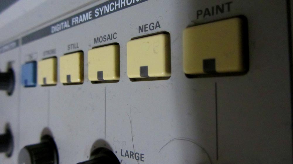
What you see in the following 3 tests are the results. Test 1 (silent) features the fine lines layered and coloured in Premiere; Test 2 (also silent) has roving lines; and Test 3 (with sound from the 110B) features the whole live scenarios in which I adjusted the mixer’s colour adjust settings, applied its digital effects (mosaic, strobe, negative), and sometimes faded to black to check the signals cleanliness. Test 3 ends abruptly because a grievous flaw in the DVD-R media caused a crap-out.
Note: Tests 1 + 2 + 3 feature flashing and strobing images, and Test 3 contains shrill audio. That said, these are best viewed on a modest sized screen in a dark environment.
TEST 1, via VIMEO and YOUTUBE:


TEST 2, via VIMEO and YOUTUBE:


TEST 3, via VIMEO and YOUTUBE:


Thanks for reading,
Mark R. Hasan, Editor
Big Head Amusement