Microtime RP-1: Questions, Questions, Questions… (UPDATED)
As the years progress, it’s becoming increasingly difficult to not only find vintage broadcast and ENG gear, but their respective manuals, detailing how more complicated / sophistimacated video gear works. The pockets of stored vintage equipment in lockers or back rooms or garages is similarly disappearing, most headed for the crusher at recycling centres, dumpsters, or the naked and cruel curbside.
If some make their way to brokers, resellers, collectors, or artists, it’s not unusual for manuals and cables to have long gone missing, if not key components necessary for proper use. Ebay’s a perfect example of what survives: the lone controllers and keyboards lacking the main unit, or the latter missing necessary keyboards; body parts scattered over years and closets and storage rooms.
With few people bearing the knowledge and functionality of those missing pieces, these dusty and encrusted chunks of metal, plastic, and rubber probably get scrapped if there’s no room or patience by the sellers wanting a quick & easy sale.
Recently, a good friend donated a standalone DVE (digital video effects unit) to the Hasonian (er, my archive), and although the original ad which appeared in the December 1988 issue of Broadcast Engineering shows the Microtime RP-1 as a standalone DVE for manipulating stills over a (presumably) live video background, without a manual, I’ve a lot of questions on its operation.
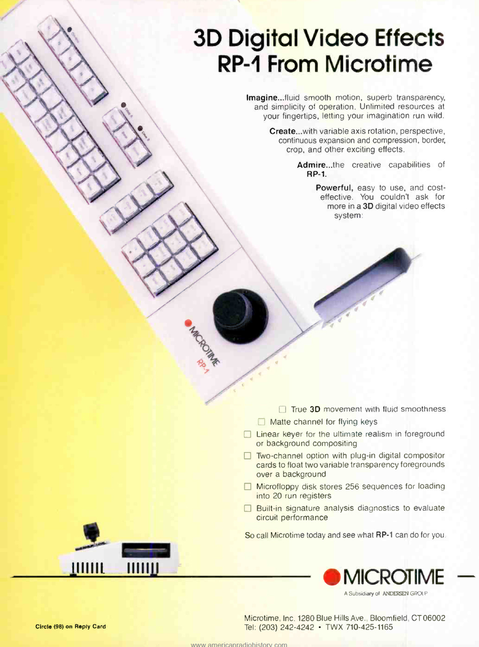
Sounds sexxxy, right? A standalone DVE, that was part of Microtime’s three-tiered offering in the late 1980s, starting at $25,000.
Comments that accompany a YouTube video hint at the rapidly evolving sophistication of Microtime’s 3D DVEs, and by the early 1990s their sophistication lay within big rackmounted brains, stacked above each other, capable of rendering real-time animation and heating a room simultaneously, as detailed in this 2020 demonstration of an Abekas A51+.
So where does Microtime’s RP-1 fit in, when there already existed big chunky component DVE’s?
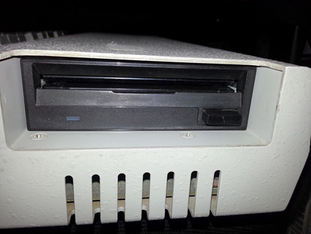
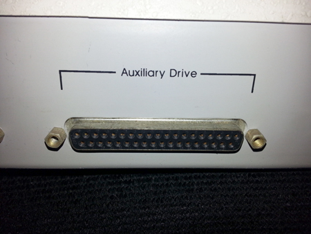
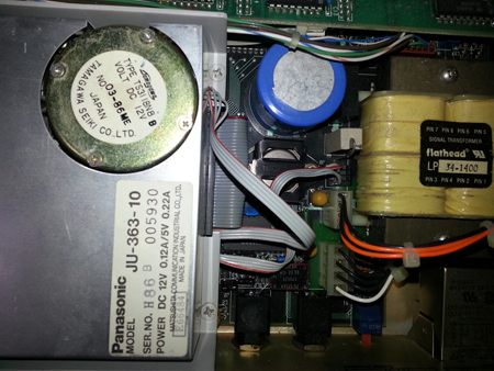
The RP-1 comes with a built-in floppy drive (a Panasonic) with a standard IDE cable for connection, and power cable hardwired to the drive and the motherboard. Drive B: is an “Auxiliary Drive” connected via a rear parallel cable, and these drives are selectable from the main menu.
After blowing out dust and cleaning the heads with isopropyl alcohol, the RP-1 was able to format a fresh floppy – but in what system? DOS? Windows DOS? Something more propriety?
If stills for animation and layering by the RP-1 come from the floppy disc, what format does the unit recognize? Targa? JPEG? GIF?
And if the stills have to be pre-loaded onto the discs from a desktop, is it a PC? What O/S? Windows 386? DOS?
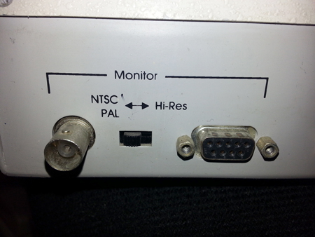
The RP-1 has a switchable Monitor Out: composite PAL / NTSC, and Hi-Res, presumably analogue RGB via a 9-pin D-sub connector.
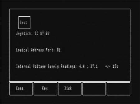
I’ve posted a short video on my YT and Vimeo channels (see Blog END for links) showing the unit’s monitor output as it powers & boots up, self-tests power, and holds on the Home screen, which is labelled TEST.
Besides switching between Drives A: and B:, the menu lets you test the illumination of the keys, in case a bulb has burnt out.

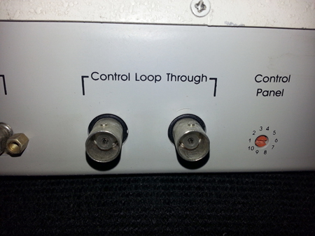
There is only one other set of connectors: Control Loop Through, through which video passes.
Does the RP-1 capture frames to a floppy for animation? Is the input purely for background video? Why is there no sync reference or genlock? Does the RP-1 employ a sync-stripper, and output a signal to which a mixer locks?
I sent in two types of video: rock solid colour bars from a Tektronix SPG, and footage from a Hi8 camera. The colours bars had phasing issues, and the camera had excessive contrast causing streaking. The camera’s signal was also initially in B&W before it snapped to colour when I zoomed into a wall – possibly the result of the circuits being smacked back to life after being unused for decades.
There’s also a small switchable potentiometer marked Control Panel with indexed 1 thru 10 settings. Adjustments don’t affect the video output, but is this tied to the looped signal, or is it similar to a SCSI setting, either for the Auxiliary Drive, or the looped out signal for keying? Note: the Control Panel appears as Logical Address Port in the Monitor Out’s main menu.
And is the outputted video supposed to contain the animated images, or should the inputted video be black or blue for keying?
If you have answers or suggestions or a scan of the manual, please post details at Big Head Amusements’ Facebook page, or in the Comments section for my YT and Vimeo excerpts.
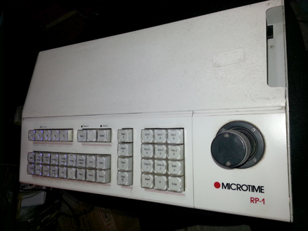
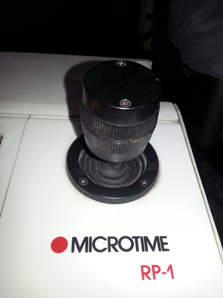
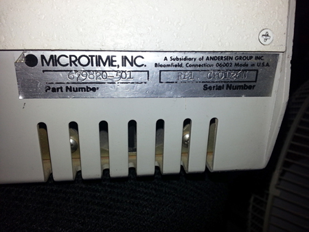
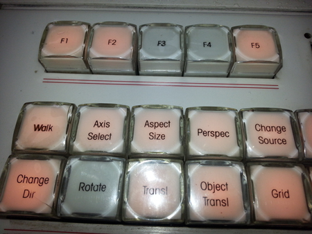
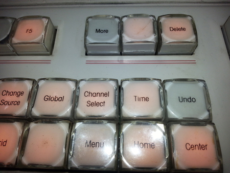
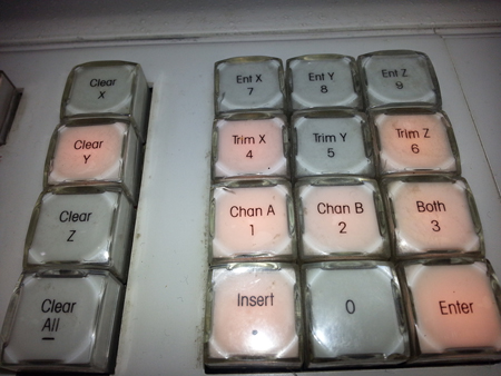
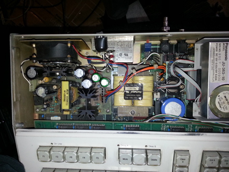
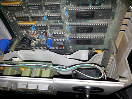
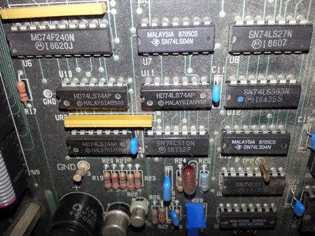
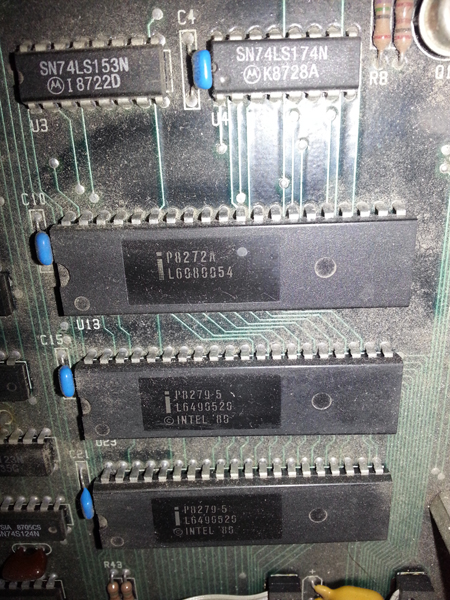
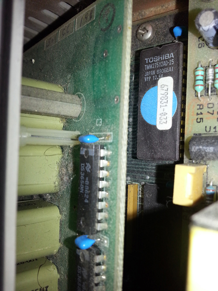
Until then, here are several stills of the RP-1, from the front, rear, and inside, with an emphasis on some of the interna ICs and 30+years of unpleasant schmutz:
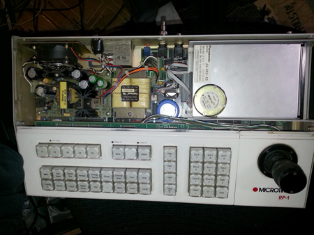

Lastly, while the short video on Vimeo & YT doesn’t show any elaborate visuals – just a boot-up, and issue-prone looped-through video – it gives a slight sampling / teasing of the mysteries that can be unearthed after a good vacuuming and scrutinizing a hefty manual…
UPDATE: November 5, 2021
I posted stills and whatever information I had tallied above in the broadcasting group Eyesofageneration.com via Facebook, and it turns out that the page advertisement is indeed deceptive, in that it lacks any image of the DVE mainframe (the brain) to which the controller is connected.
I stitched together several posts from the group below for narrative clarity:
BNC control could be 50 ohm 10BASE2 Thin Ethernet – that would have been available in 1988.
Ampex produced the ADO 100, a new generation ADO with a smaller form factor. It used 50ohm 10base2, of course requiring its own cable run.
All those DVE keyboards of the time were connected to a box in the machine room or under the console.
And required massive cooling for all the ICs.
From what I remember, it was a two channel DVE. We had the single chan. Microtime ACT-1 in college. Also had control panel & mainframe. The engineers use to call it a meat grinder as the video you routed to it just looked bad.
Microtime produced several more sophisticated real time DVEs. including the ACT 1, and the Impact, which is showcased in this demo video from the early 1990s:
So… for the time being, I’ve either a movie prop with blinky-blinky lights, or a body now in storage waiting to be connected to its mega-brain. At least I know it turns on, boots up, will format the floppy in a Raw file system / old FAT system, and responds to basic keyboard selections. In other words, it works, but only to a slight point, and if this YouTube video is a sampling of the bulk, heat, hydro usage, and patience required to work one of this real-time beasts, I’d need a large studio and more than a few weekends to learn and use the monster.
This demonstration of an Abekas A51+ also validates the need for time, patience, and a manual for this complicated devices:
A monster indeed. And, er, I wouldn’t object to owning one, should the opportunity arise 🙂
Thanks for reading,
Mark R. Hasan, Editor
Big Head Amusements